Datasheet TS555 (STMicroelectronics) - 5
| Производитель | STMicroelectronics |
| Описание | Low-power single CMOS timer |
| Страниц / Страница | 19 / 5 — TS555. Schematic diagrams. Figure 2. Block diagram. Table 3. Functional … |
| Формат / Размер файла | PDF / 434 Кб |
| Язык документа | английский |
TS555. Schematic diagrams. Figure 2. Block diagram. Table 3. Functional table. Reset. Trigger. Threshold. Output
57 предложений от 31 поставщиков Интегральные микросхемы Тактовые микросхемы - Программируемые таймеры и Генераторы |
| TS555CD
STMicroelectronics | 11 ₽ | |
| TS555IDT
Texas Instruments | 14 ₽ | |
| TS555CDT
STMicroelectronics | 20 ₽ | |
| TS555IPT
STMicroelectronics | 20 ₽ | |
Модельный ряд для этого даташита
Текстовая версия документа
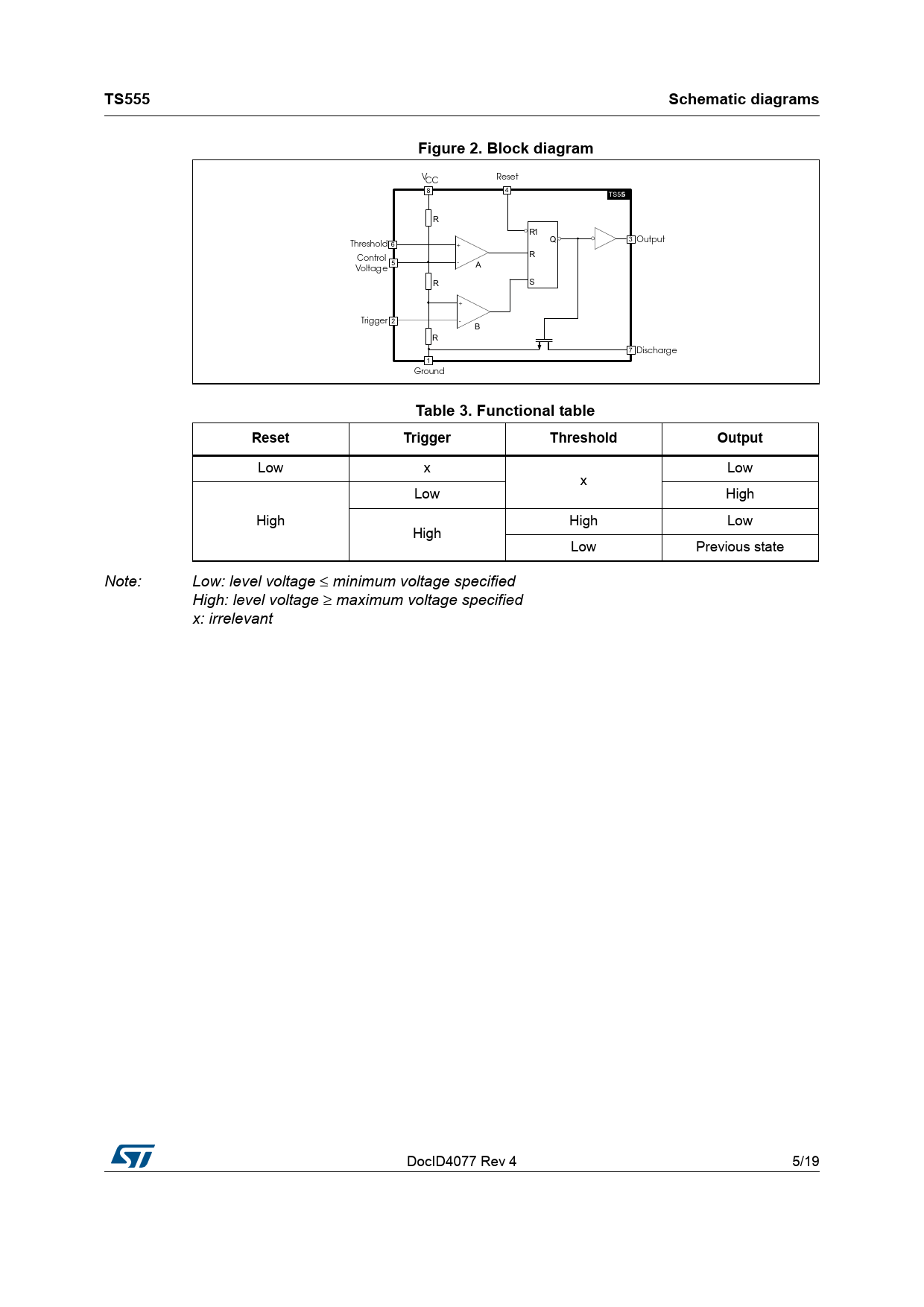
TS555 Schematic diagrams Figure 2. Block diagram
6## 2ESET 76 5 5 4 /UTPUT 4HRESHOLD #ONTROL 5 6OLTAG E $ 5 6 4RIGGER % 5 $ISCHARGE 'ROUND
Table 3. Functional table Reset Trigger Threshold Output
Low x Low x Low High High High Low High Low Previous state Note: Low: level voltage ≤ minimum voltage specified High: level voltage ≥ maximum voltage specified x: irrelevant DocID4077 Rev 4 5/19 19 Document Outline 1 Absolute maximum ratings and operating conditions Table 1. Absolute maximum ratings Table 2. Operating conditions 2 Schematic diagrams Figure 1. Schematic diagram Figure 2. Block diagram Table 3. Functional table 3 Electrical characteristics Table 4. Static electrical characteristics VCC = +2 V, Tamb = +25 °C, reset to VCC (unless otherwise specified) Table 5. Static electrical characteristics VCC = +3 V, Tamb = +25 °C, reset to VCC (unless otherwise specified) Table 6. Dynamic electrical characteristics VCC = +3 V, Tamb = +25 °C, reset to VCC (unless otherwise specified) Table 7. Static electrical characteristics VCC = +5 V, Tamb = +25 °C, reset to VCC (unless otherwise specified) Table 8. Dynamic electrical characteristics VCC = +5 V, Tamb = +25 °C, reset to VCC (unless otherwise specified) Table 9. Static electrical characteristics VCC = +12 V, Tamb = +25 °C, reset to VCC (unless otherwise specified) Table 10. Dynamic electrical characteristics VCC = +12 V, Tamb = +25 °C, reset to VCC (unless otherwise specified) Figure 3. Supply current (per timer) versus supply voltage 4 Application information 4.1 Monostable operation Figure 4. Application schematic Figure 5. Timing diagram 4.2 Astable operation Figure 6. Application schematic Figure 7. Timing diagram 5 Package information 5.1 SO8 package information Figure 8. SO8 package outline Table 11. SO8 mechanical data 6 Ordering information Table 12. Order code table 7 Revision history Table 13. Document revision history

 Купить TS555 на РадиоЛоцман.Цены — от 11 до 214 ₽


