Preliminary Datasheet EPC23102 (Efficient Power Conversion) - 3
| Производитель | Efficient Power Conversion |
| Описание | ePower Stage IC |
| Страниц / Страница | 15 / 3 — eGaN® FET DATASHEET. Absolute Maximum Ratings. SYMBOL. PARAMETER. MIN. … |
| Формат / Размер файла | PDF / 1.6 Мб |
| Язык документа | английский |
eGaN® FET DATASHEET. Absolute Maximum Ratings. SYMBOL. PARAMETER. MIN. MAX. UNITS. ESD Ratings. Thermal Characteristics. TYP

8 предложений от 2 поставщиков IC HALF BRIDGE DRIVER 35A 13WQFN |
| EPC23102ENGRT
Efficient Power Conversion | от 134 ₽ | |
| EPC23102ENGRT
Efficient Power Conversion | по запросу | |
Модельный ряд для этого даташита
Текстовая версия документа
eGaN® FET DATASHEET
EPC23102
Absolute Maximum Ratings
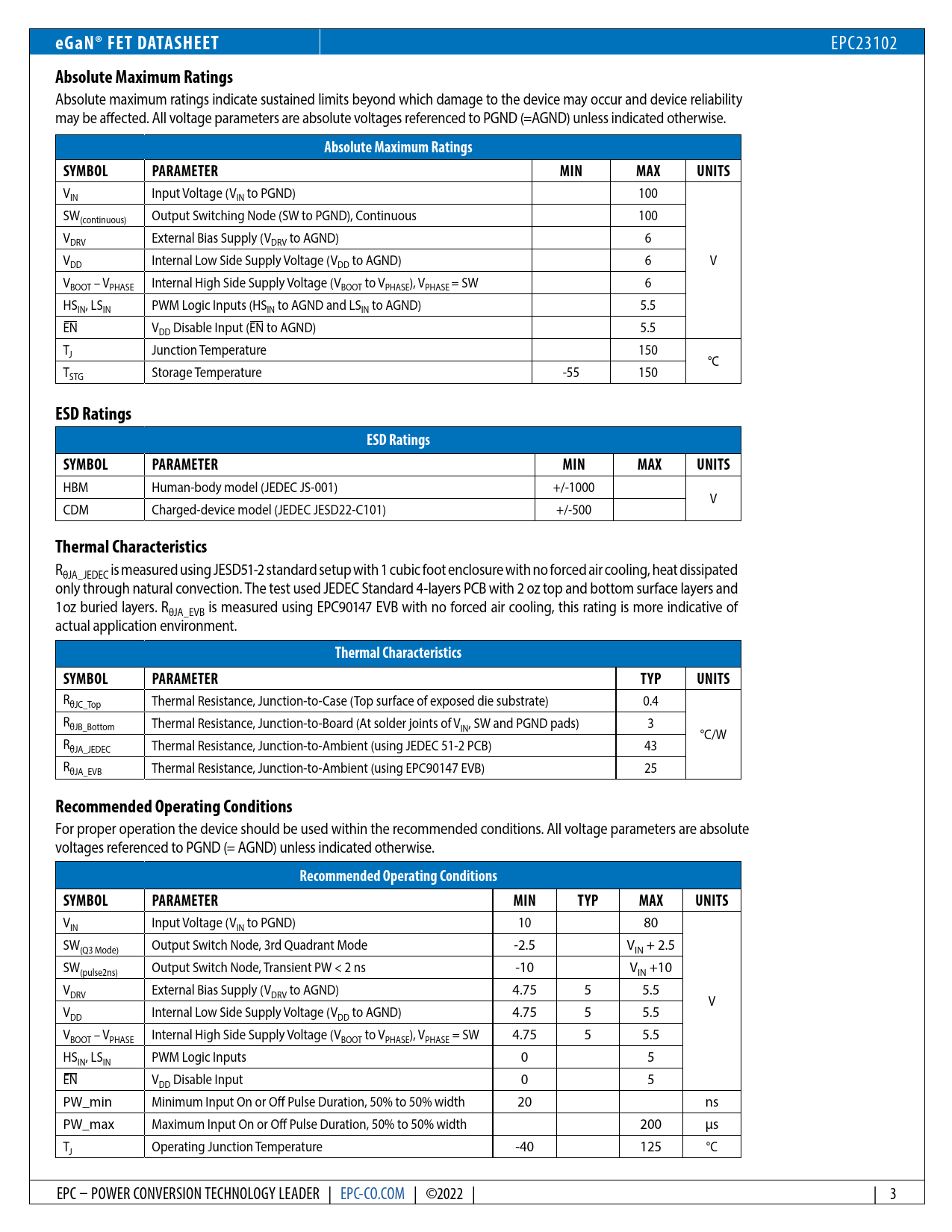
Absolute maximum ratings indicate sustained limits beyond which damage to the device may occur and device reliability may be affected. All voltage parameters are absolute voltages referenced to PGND (=AGND) unless indicated otherwise.
Absolute Maximum Ratings SYMBOL PARAMETER MIN MAX UNITS
VIN Input Voltage (VIN to PGND) 100 SW(continuous) Output Switching Node (SW to PGND), Continuous 100 VDRV External Bias Supply (VDRV to AGND) 6 V V DD Internal Low Side Supply Voltage (VDD to AGND) 6 VBOOT – VPHASE Internal High Side Supply Voltage (VBOOT to VPHASE), VPHASE = SW 6 HSIN, LSIN PWM Logic Inputs (HSIN to AGND and LSIN to AGND) 5.5 EN VDD Disable Input (EN to AGND) 5.5 TJ Junction Temperature 150 °C TSTG Storage Temperature -55 150
ESD Ratings ESD Ratings SYMBOL PARAMETER MIN MAX UNITS
HBM Human-body model (JEDEC JS-001) +/-1000 V CDM Charged-device model (JEDEC JESD22-C101) +/-500
Thermal Characteristics
RθJA_JEDEC is measured using JESD51-2 standard setup with 1 cubic foot enclosure with no forced air cooling, heat dissipated only through natural convection. The test used JEDEC Standard 4-layers PCB with 2 oz top and bottom surface layers and 1 oz buried layers. RθJA_EVB is measured using EPC90147 EVB with no forced air cooling, this rating is more indicative of actual application environment.
Thermal Characteristics SYMBOL PARAMETER TYP UNITS
RθJC_Top Thermal Resistance, Junction-to-Case (Top surface of exposed die substrate) 0.4 RθJB_Bottom Thermal Resistance, Junction-to-Board (At solder joints of VIN, SW and PGND pads) 3 °C/W RθJA_JEDEC Thermal Resistance, Junction-to-Ambient (using JEDEC 51-2 PCB) 43 RθJA_EVB Thermal Resistance, Junction-to-Ambient (using EPC90147 EVB) 25
Recommended Operating Conditions
For proper operation the device should be used within the recommended conditions. All voltage parameters are absolute voltages referenced to PGND (= AGND) unless indicated otherwise.
Recommended Operating Conditions SYMBOL PARAMETER MIN TYP MAX UNITS
VIN Input Voltage (VIN to PGND) 10 80 SW(Q3 Mode) Output Switch Node, 3rd Quadrant Mode -2.5 VIN + 2.5 SW(pulse2ns) Output Switch Node, Transient PW < 2 ns -10 VIN +10 VDRV External Bias Supply (VDRV to AGND) 4.75 5 5.5 V VDD Internal Low Side Supply Voltage (VDD to AGND) 4.75 5 5.5 VBOOT – VPHASE Internal High Side Supply Voltage (VBOOT to VPHASE), VPHASE = SW 4.75 5 5.5 HSIN, LSIN PWM Logic Inputs 0 5 EN VDD Disable Input 0 5 PW_min Minimum Input On or Off Pulse Duration, 50% to 50% width 20 ns PW_max Maximum Input On or Off Pulse Duration, 50% to 50% width 200 µs TJ Operating Junction Temperature -40 125 °C EPC – POWER CONVERSION TECHNOLOGY LEADER | EPC-CO.COM | ©2022 | | 3
