Datasheet AEM00940 (E-peas) - 5
| Производитель | E-peas |
| Описание | Highly efficient, regulated dual-output, ambient energy manager for Source Voltage Level Configuration with optional primary battery |
| Страниц / Страница | 29 / 5 — DATASHEET. AEM00940. 1. Introduction |
| Формат / Размер файла | PDF / 2.2 Мб |
| Язык документа | английский |
DATASHEET. AEM00940. 1. Introduction

Модельный ряд для этого даташита
Текстовая версия документа
link to page 21 link to page 13
DATASHEET AEM00940
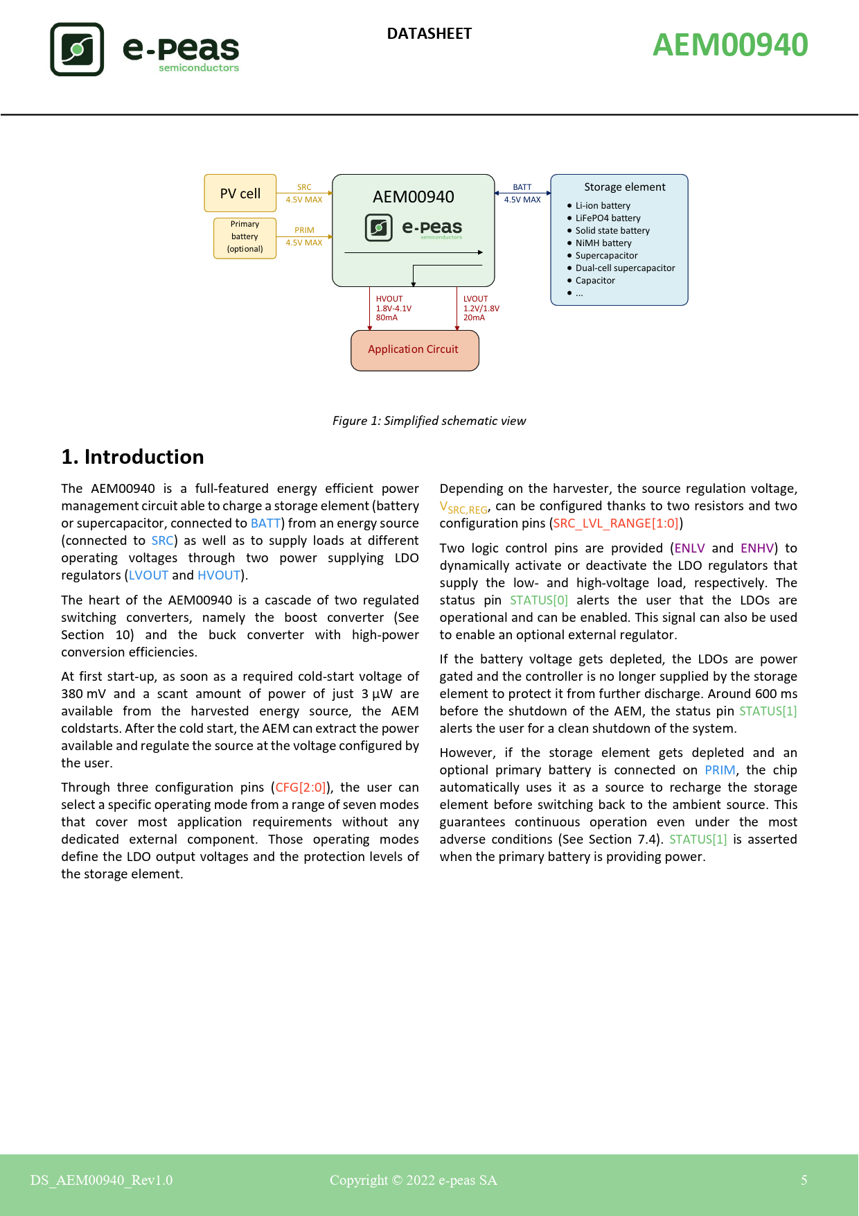
SRC BATT PV cell Storage element 4.5V MAX AEM00940 4.5V MAX Li-ion battery LiFePO4 battery Primary PRIM Solid state battery battery 4.5V MAX NiMH battery (optional) Supercapacitor Dual-cell supercapacitor Capacitor ... HVOUT LVOUT 1.8V-4.1V 1.2V/1.8V 80mA 20mA Application Circuit Figure 1: Simplified schematic view
1. Introduction
The AEM00940 is a ful -featured energy efficient power Depending on the harvester, the source regulation voltage, management circuit able to charge a storage element (battery VSRC,REG, can be configured thanks to two resistors and two or supercapacitor, connected to BATT) from an energy source configuration pins (SRC_LVL_RANGE[1:0]) (connected to SRC) as wel as to supply loads at different Two logic control pins are provided (ENLV and ENHV) to operating voltages through two power supplying LDO dynamical y activate or deactivate the LDO regulators that regulators (LVOUT and HVOUT). supply the low- and high-voltage load, respectively. The The heart of the AEM00940 is a cascade of two regulated status pin STATUS[0] alerts the user that the LDOs are switching converters, namely the boost converter (See operational and can be enabled. This signal can also be used Section 10) and the buck converter with high-power to enable an optional external regulator. conversion efficiencies. If the battery voltage gets depleted, the LDOs are power At first start-up, as soon as a required cold-start voltage of gated and the control er is no longer supplied by the storage 380 mV and a scant amount of power of just 3 µW are element to protect it from further discharge. Around 600 ms available from the harvested energy source, the AEM before the shutdown of the AEM, the status pin STATUS[1] coldstarts. After the cold start, the AEM can extract the power alerts the user for a clean shutdown of the system. available and regulate the source at the voltage configured by However, if the storage element gets depleted and an the user. optional primary battery is connected on PRIM, the chip Through three configuration pins (CFG[2:0]), the user can automatical y uses it as a source to recharge the storage select a specific operating mode from a range of seven modes element before switching back to the ambient source. This that cover most application requirements without any guarantees continuous operation even under the most dedicated external component. Those operating modes adverse conditions (See Section 7.4). STATUS[1] is asserted define the LDO output voltages and the protection levels of when the primary battery is providing power. the storage element. DS D _A _ E A M0 M 094 9 0_Rev e 1.0. 0 0 Copyr y ight h © 2022 2 e-pe p as a SA S Confidential 5 Document Outline 1. Introduction 2. Absolute Maximum Ratings 3. Thermal Resistance 4. Typical Electrical Characteristics at 25 °C 5. Recommended Operation Conditions 6. Functional Block Diagram 7. Theory of Operation 7.1. Deep sleep & Wake up modes 7.1.1. Supercapacitor as a storage element. 7.1.2. Battery as a storage element. 7.2. Normal mode 7.2.1. Boost 7.2.2. Buck 7.2.3. LDO outputs 7.3. Overcharge mode 7.4. Primary mode 7.5. Shutdown mode 7.6. Balun for dual-cell supercapacitor 8. System configuration 8.1. Battery and LDOs configuration 8.1.1. Custom mode 8.2. Source voltage configuration 8.3. Primary battery configuration 8.4. No-battery configuration 8.5. Storage element information 8.6. External inductors information 8.7. External capacitors information 9. Typical Application Circuits 9.1. Example circuit 1 9.2. Example circuit 2 10. Performance Data 10.1. BOOST conversion efficiency for LBOOST = 10 µH 10.2. BOOST conversion efficiency for LBOOST = 22 µH 10.3. Quiescent current 10.4. High-voltage LDO regulation 10.5. Low-voltage LDO regulation 10.6. High-voltage LDO efficiency 10.7. Low-voltage LDO efficiency 11. Schematic 12. Layout Package Information 13.1. Plastic Quad Flatpack No-lead (QFN 28-pin 5x5mm) 13.2. Board Layout 14. Revision History
