Datasheet AS2333 (Diodes) - 2
| Производитель | Diodes |
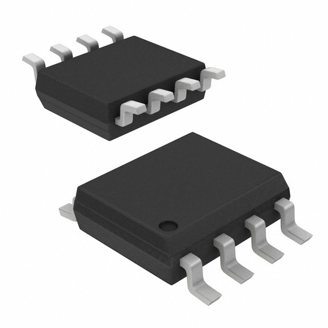
| Описание | 1.8V, Micropower CMOS Zero-Drift Operational Amplifiers |
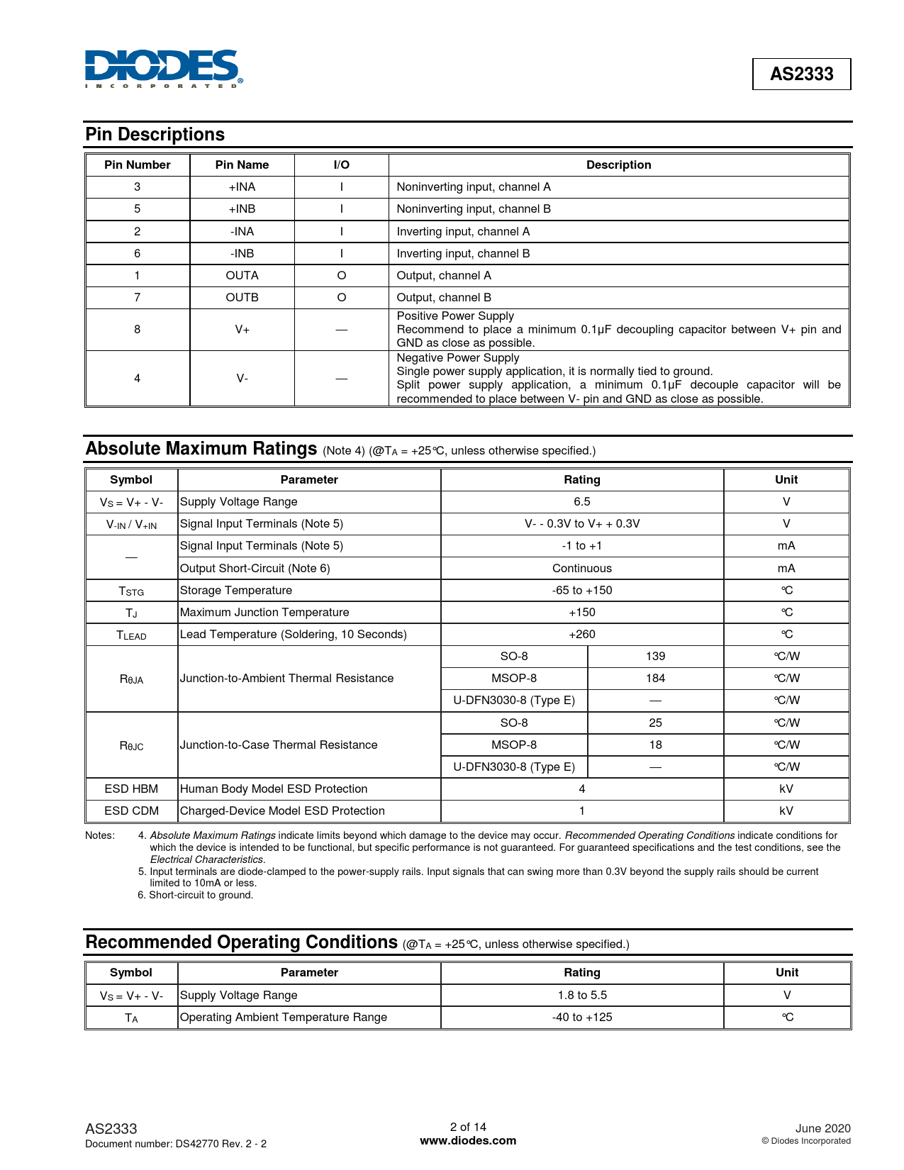
| Страниц / Страница | 14 / 2 — AS2333. Pin Descriptions. Pin Number. Pin Name. I/O. Description. … |
| Формат / Размер файла | PDF / 788 Кб |
| Язык документа | английский |
AS2333. Pin Descriptions. Pin Number. Pin Name. I/O. Description. Absolute Maximum Ratings. Symbol. Parameter. Rating. Unit

42 предложений от 13 поставщиков Операционный усилитель, 1 Усилитель, 350 кГц, 0.12 В/мкс, 1.8В до 5.5В, SOIC, 8 вывод(-ов) |
| AS2333S-13
Diodes | от 21 ₽ | |
| AS2333S-13
Diodes | от 60 ₽ | |
| AS2333S-13
Diodes | от 82 ₽ | |
| AS2333S13
| 3 478 ₽ | |
Модельный ряд для этого даташита
Текстовая версия документа
AS2333 Pin Descriptions Pin Number Pin Name I/O Description
3 +INA I Noninverting input, channel A 5 +INB I Noninverting input, channel B 2 -INA I Inverting input, channel A 6 -INB I Inverting input, channel B 1 OUTA O Output, channel A 7 OUTB O Output, channel B Positive Power Supply 8 V+ — Recommend to place a minimum 0.1μF decoupling capacitor between V+ pin and GND as close as possible. Negative Power Supply Single power supply application, it is normally tied to ground. 4 V- — Split power supply application, a minimum 0.1μF decouple capacitor will be recommended to place between V- pin and GND as close as possible.
Absolute Maximum Ratings
(Note 4) (@TA = +25°C, unless otherwise specified.)
Symbol Parameter Rating Unit
VS = V+ - V- Supply Voltage Range 6.5 V V-IN / V+IN Signal Input Terminals (Note 5) V- - 0.3V to V+ + 0.3V V Signal Input Terminals (Note 5) -1 to +1 mA — Output Short-Circuit (Note 6) Continuous mA TSTG Storage Temperature -65 to +150 °C TJ Maximum Junction Temperature +150 °C TLEAD Lead Temperature (Soldering, 10 Seconds) +260 °C SO-8 139 °C/W RθJA Junction-to-Ambient Thermal Resistance MSOP-8 184 °C/W U-DFN3030-8 (Type E) — °C/W SO-8 25 °C/W RθJC Junction-to-Case Thermal Resistance MSOP-8 18 °C/W U-DFN3030-8 (Type E) — °C/W ESD HBM Human Body Model ESD Protection 4 kV ESD CDM Charged-Device Model ESD Protection 1 kV Notes: 4. Absolute Maximum Ratings indicate limits beyond which damage to the device may occur. Recommended Operating Conditions indicate conditions for which the device is intended to be functional, but specific performance is not guaranteed. For guaranteed specifications and the test conditions, see the Electrical Characteristics. 5. Input terminals are diode-clamped to the power-supply rails. Input signals that can swing more than 0.3V beyond the supply rails should be current limited to 10mA or less. 6. Short-circuit to ground.
Recommended Operating Conditions
(@TA = +25°C, unless otherwise specified.)
Symbol Parameter Rating Unit
VS = V+ - V- Supply Voltage Range 1.8 to 5.5 V TA Operating Ambient Temperature Range -40 to +125 °C AS2333 2 of 14 June 2020 Document number: DS42770 Rev. 2 - 2
www.diodes.com
© Diodes Incorporated

 Купить AS2333S-13 на РадиоЛоцман.Цены — от 21 до 3 478 ₽