Datasheet BM90 (Microchip) - 4
| Производитель | Microchip |
| Описание | Bluetooth 3.0 Multi-Speaker Stereo Audio Module |
| Страниц / Страница | 31 / 4 — BM90 Module. Abbreviations List: HFP:. AVRCP:. A2DP:. PBAP:. HSP:. SPP:. … |
| Формат / Размер файла | PDF / 1.7 Мб |
| Язык документа | английский |
BM90 Module. Abbreviations List: HFP:. AVRCP:. A2DP:. PBAP:. HSP:. SPP:. NFC:. SCMS-T. 1.0 DEVICE OVERVIEW

Модельный ряд для этого даташита
Текстовая версия документа
link to page 4
BM90 Module Abbreviations List: HFP:
Hands-free Profile
AVRCP:
Audio Video Remote Control Profile
A2DP:
Advanced Audio Distribution Profile
PBAP:
Phone Book Access Profile
HSP:
Headset Profile
SPP:
Serial Port Profile
NFC:
Near Field Communication
SCMS-T
:Serial Copy Management System
1.0 DEVICE OVERVIEW
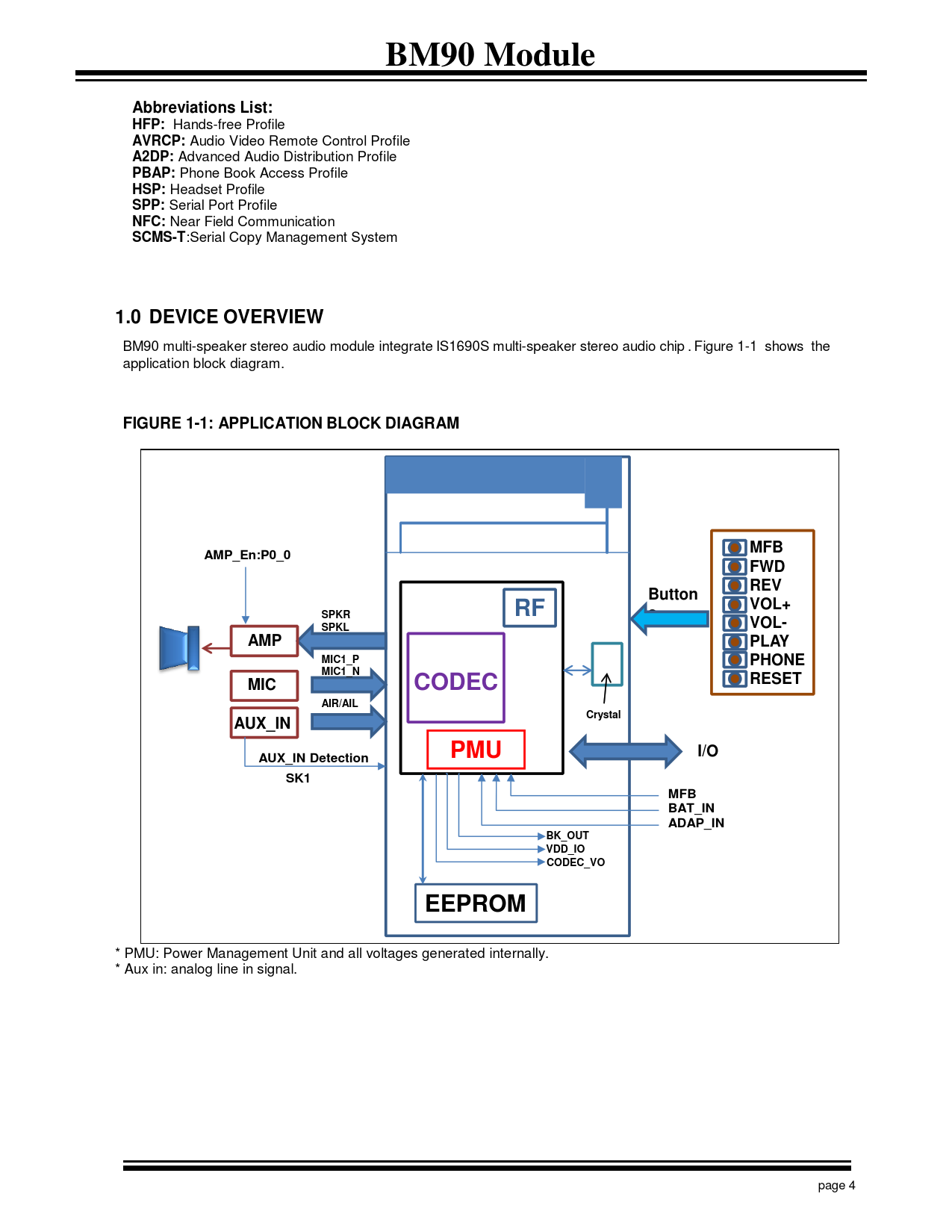
BM90 multi-speaker stereo audio module integrate IS1690S multi-speaker stereo audio chip . Figure 1-1 shows the application block diagram.
FIGURE 1-1: APPLICATION BLOCK DIAGRAM MFB AMP_En:P0_0 FWD REV Button VOL+ SPKR RF s SPKL VOL- AMP PLAY MIC1_P PHONE MIC1_N RESET MIC CODEC AIR/AIL Crystal AUX_IN PMU I/O AUX_IN Detection SK1 MFB BAT_IN ADAP_IN BK_OUT VDD_IO CODEC_VO EEPROM
* PMU: Power Management Unit and all voltages generated internally. * Aux in: analog line in signal. page 4 Document Outline Bluetooth® 3.0 Multi-Speaker Stereo Audio Module Features Description Applications Table of Contents 1.0 DEVICE OVERVIEW FIGURE 1-1: APPLICATION BLOCK DIAGRAM Audio Interface FIGURE 1-2: Analog audio interface block diagram FIGURE 1-3: Twin Speaker Link block diagram 2.0 Key Features Table 3.0 PIN DESCRIPTION TABLE 3-1: BM90 PIN DESCRIPTION 4.0 SPECIFICATIONS 4.1 SPECIFICATIONS Table 4-1: Absolute Maximum Specifications Table 4-2: Recommended operating condition Table 4-3: Battery Charger Table 4-4: LED driver Table 4-5: Digital IO Table 4-6: Audio codec Digital to Analogue Converter Table 4-7: Audio codec Analogue to Digital Converter Table 4-8: Transmitter section for BDR Table 4-9: Transmitter section for EDR Table 4-10: Receiver section for BDR Table 4-11: Receiver section for EDR 4.2 PRINTED ANTENNA PERFORMANCE Table 4-12: Antenna Parameters FIGURE 4-1: Antenna 3D radiation pattern @2441 MHz 4.3 BQTF INFORMATION FIGURE 4-2: BQTF Information 4.4 CURRENT CONSUMPTION Table 4-13: Single Mode current consumption Table 4-14: Twin Mode: Master current consumption Table 4-15: Twin Mode: Slave current consumption 5.0 APPLICATIONS 5.1 EXTERNAL CONFIGURATION FIGURE 5-1: External Configuration Header Connections TABLE 5-1: SYSTEM CONFIGURATION SETTINGS 5.2 LED DRIVER 5.3 FUNCTION OF PIN TABLE 5-2: IOs for Buttons TABLE 5-3: IOs for added functions 5.4 Adaptive Frequency Hopping (AFH) 5.5 MULTI-SPEAKER 5.5.1 TWIN SPEAKER LINK TECHNOLOGY INTRODUCTION 5.5.1.1 TWIN SPEAKER LINK Figure 5-2 A2DP Twin Speaker Link Diagram 5.6 Mounting Details 5.7 Module Dimension FIGURE 5-3: BM90 module FIGURE 5-4: Outline Dimension FIGURE 5-5: Module Foot print 5.8 Main Board Antenna Area Layout Guide FIGURE 5-6: Mother Board Antenna Area Layout Guide 5.9 RFLOW PROFILE 5.9.1Soldering Recommendations FIGURE 5-7: Reflow profile 6.0 REFERENCE CIRCUIT FIGURE 6-1: BM90 reference circuit 7.0 PACKING INFORMATION 7.1 QR code label information 7.2 Storage standard 7.3 Ordering Information 7.4 Tray Dimensions 7.5 Packing Method