Datasheet IX4351NE (IXYS) - 5
| Производитель | IXYS |
| Описание | 9A Low Side SiC MOSFET & IGBT Driver |
| Страниц / Страница | 12 / 5 — IX4351NE. Parameter. Conditions. Symbol. Minimum. Typical. Maximum. … |
| Формат / Размер файла | PDF / 334 Кб |
| Язык документа | английский |
IX4351NE. Parameter. Conditions. Symbol. Minimum. Typical. Maximum. Units. www.ixysic.com

Модельный ряд для этого даташита
Текстовая версия документа
I
IX4351NE
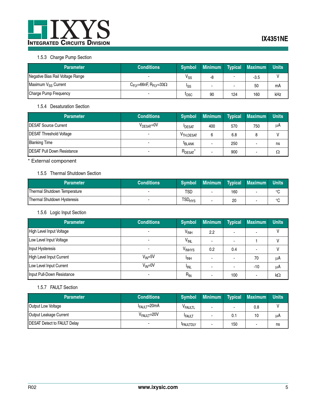
NTEGRATED CIRCUITS DIVISION 1.5.3 Charge Pump Section
Parameter Conditions Symbol Minimum Typical Maximum Units
Negative Bias Rail Voltage Range - VSS -8 - -3.5 V Maximum VSS Current CFLY=66nF, RFLY=33 ISS - - 50 mA Charge Pump Frequency - fOSC 90 124 160 kHz 1.5.4 Desaturation Section
Parameter Conditions Symbol Minimum Typical Maximum Units
DESAT Source Current VDESAT=0V IDESAT 400 570 750 A DESAT Threshold Voltage - VTH,DESAT 6 6.8 8 V Blanking Time - tBLANK - 250 - ns DESAT Pull Down Resistance - RDESAT* - 900 - * External component 1.5.5 Thermal Shutdown Section
Parameter Conditions Symbol Minimum Typical Maximum Units
Thermal Shutdown Temperature - TSD - 160 - °C Thermal Shutdown Hysteresis - TSDHYS - 20 - °C 1.5.6 Logic Input Section
Parameter Conditions Symbol Minimum Typical Maximum Units
High Level Input Voltage - VINH 2.2 - - V Low Level Input Voltage - VINL - - 1 V Input Hysteresis - VINHYS 0.2 0.4 - V High Level Input Current VIN=5V IINH - - 70 A Low Level Input Current VIN=0V IINL - - -10 A Input Pull-Down Resistance - RIN - 100 - k 1.5.7 FAULT Section
Parameter Conditions Symbol Minimum Typical Maximum Units
Output Low Voltage IFAULT=20mA VFAULTL - - 0.8 V Output Leakage Current VFAULT=20V IFAULT - 0.1 10 A DESAT Detect to FAULT Delay - tFAULTDLY - 150 - ns R02
www.ixysic.com
5 Document Outline Features Applications Description Ordering Information 1 Specifications 1.1 Package Pinout 1.2 Pin Description 1.3 Absolute Maximum Ratings 1.4 Recommended Operating Conditions 1.5 Electrical Characteristics 1.6 Thermal Characteristics 2 Performance Data 3 Performance Data (Cont.) 4 Functional Description 4.1 Logic Input (IN) 4.2 Gate Drive Outputs (OUTSRC and OUTSNK) 4.3 Internal 4.6V Regulator (VREG) 4.4 Negative VSS Charge Pump Regulator 4.5 Desaturation Detection and Protection 4.6 Thermal Shutdown 4.7 FAULT Output 5 Manufacturing Information 5.1 Moisture Sensitivity 5.2 ESD Sensitivity 5.3 Soldering Profile 5.4 Board Wash 5.5 Mechanical Dimensions
