Datasheet TLP5231 (Toshiba) - 7
| Производитель | Toshiba |
| Описание | Photocouplers. Infrared LED & Photo IC |
| Страниц / Страница | 30 / 7 — TLP5231. 9.2. Electrical. Characteristics. (Note). (Unless. otherwise. … |
| Формат / Размер файла | PDF / 1.8 Мб |
| Язык документа | английский |
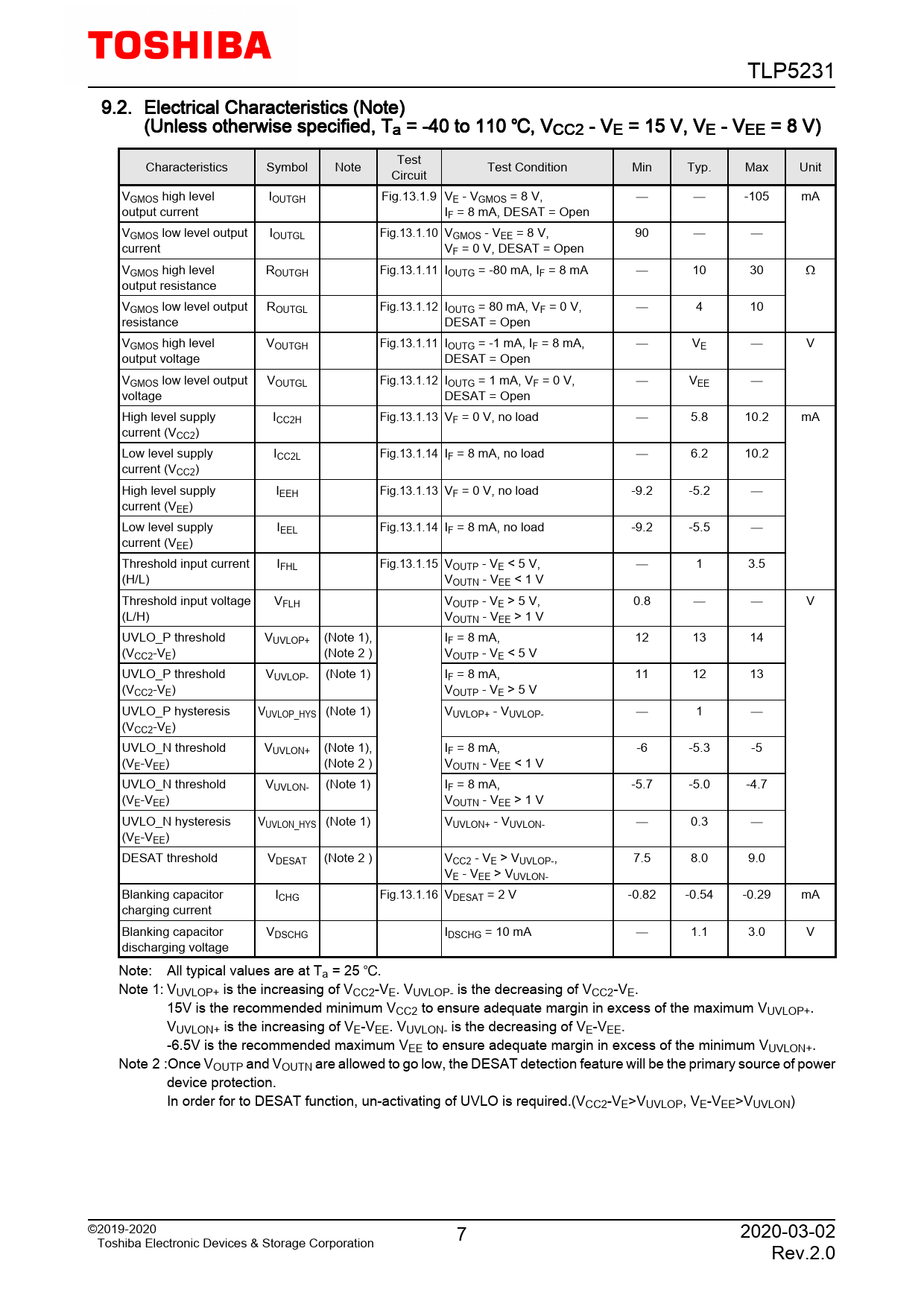
TLP5231. 9.2. Electrical. Characteristics. (Note). (Unless. otherwise. specified,. Ta. =. -40. to. 110. ,. VCC2. -. VE. =. 15. V,. VE. -. VEE. =. 8. V). Test

Модельный ряд для этого даташита
Текстовая версия документа
TLP5231 9.2. Electrical Characteristics (Note) (Unless otherwise specified, Ta = -40 to 110 , VCC2 - VE = 15 V, VE - VEE = 8 V) Test Characteristics Symbol Note Test Condition Min Typ. Max Unit Circuit VGMOS high level IOUTGH Fig.13.1.9 VE - VGMOS = 8 V, -105 mA output current IF = 8 mA, DESAT = Open VGMOS low level output IOUTGL Fig.13.1.10 VGMOS - VEE = 8 V, 90 current VF = 0 V, DESAT = Open VGMOS high level ROUTGH Fig.13.1.11 IOUTG = -80 mA, IF = 8 mA 10 30 Ω output resistance VGMOS low level output ROUTGL Fig.13.1.12 IOUTG = 80 mA, VF = 0 V, 4 10 resistance DESAT = Open VGMOS high level VOUTGH Fig.13.1.11 IOUTG = -1 mA, IF = 8 mA, VE V output voltage DESAT = Open VGMOS low level output VOUTGL Fig.13.1.12 IOUTG = 1 mA, VF = 0 V, VEE voltage DESAT = Open High level supply ICC2H Fig.13.1.13 VF = 0 V, no load 5.8 10.2 mA current (VCC2) Low level supply ICC2L Fig.13.1.14 IF = 8 mA, no load 6.2 10.2 current (VCC2) High level supply IEEH Fig.13.1.13 VF = 0 V, no load -9.2 -5.2 current (VEE) Low level supply IEEL Fig.13.1.14 IF = 8 mA, no load -9.2 -5.5 current (VEE) Threshold input current IFHL Fig.13.1.15 VOUTP - VE < 5 V, 1 3.5 (H/L) VOUTN - VEE < 1 V Threshold input voltage VFLH VOUTP - VE > 5 V, 0.8 V (L/H) VOUTN - VEE > 1 V UVLO_P threshold VUVLOP+ (Note 1), IF = 8 mA, 12 13 14 (VCC2-VE) (Note 2 ) VOUTP - VE < 5 V UVLO_P threshold VUVLOP- (Note 1) IF = 8 mA, 11 12 13 (VCC2-VE) VOUTP - VE > 5 V UVLO_P hysteresis VUVLOP_HYS (Note 1) VUVLOP+ - VUVLOP- 1 (VCC2-VE) UVLO_N threshold VUVLON+ (Note 1), IF = 8 mA, -6 -5.3 -5 (VE-VEE) (Note 2 ) VOUTN - VEE < 1 V UVLO_N threshold VUVLON- (Note 1) IF = 8 mA, -5.7 -5.0 -4.7 (VE-VEE) VOUTN - VEE > 1 V UVLO_N hysteresis VUVLON_HYS (Note 1) VUVLON+ - VUVLON- 0.3 (VE-VEE) DESAT threshold VDESAT (Note 2 ) VCC2 - VE > VUVLOP-, 7.5 8.0 9.0 VE - VEE > VUVLON- Blanking capacitor ICHG Fig.13.1.16 VDESAT = 2 V -0.82 -0.54 -0.29 mA charging current Blanking capacitor VDSCHG IDSCHG = 10 mA 1.1 3.0 V discharging voltage Note: All typical values are at Ta = 25 . Note 1: VUVLOP+ is the increasing of VCC2-VE. VUVLOP- is the decreasing of VCC2-VE. 15V is the recommended minimum VCC2 to ensure adequate margin in excess of the maximum VUVLOP+. VUVLON+ is the increasing of VE-VEE. VUVLON- is the decreasing of VE-VEE. -6.5V is the recommended maximum VEE to ensure adequate margin in excess of the minimum VUVLON+. Note 2 :Once VOUTP and VOUTN are allowed to go low, the DESAT detection feature will be the primary source of power device protection. In order for to DESAT function, un-activating of UVLO is required.(VCC2-VE>VUVLOP, VE-VEE>VUVLON) ©2019-2020 7 2020-03-02 Toshiba Electronic Devices & Storage Corporation Rev.2.0

 Купить TLP5231 на РадиоЛоцман.Цены — от 260 до 23 124 ₽