Datasheet 6N138, 6N139 (Toshiba) - 4
| Производитель | Toshiba |
| Описание | Photocoupler IRED & Photo IC |
| Страниц / Страница | 6 / 4 — Switching Specifications (Ta=25°C, VCC=5V, unless otherwise specified) |
| Формат / Размер файла | PDF / 308 Кб |
| Язык документа | английский |
Switching Specifications (Ta=25°C, VCC=5V, unless otherwise specified)

78 предложений от 35 поставщиков Оптопара, с выходом Дарлингтона, 1 канал, DIP, 8 вывод(-ов), 20 мА, 5 кВ, 500 % |
| EL6N139
Everlight | от 11 ₽ | |
| EL6N139
Everlight | от 11 ₽ | |
| 6N139
Fairchild | по запросу | |
| 6N139-V
Everlight | по запросу | |
Модельный ряд для этого даташита
Текстовая версия документа
6N138,6N139
Switching Specifications (Ta=25°C, VCC=5V, unless otherwise specified)
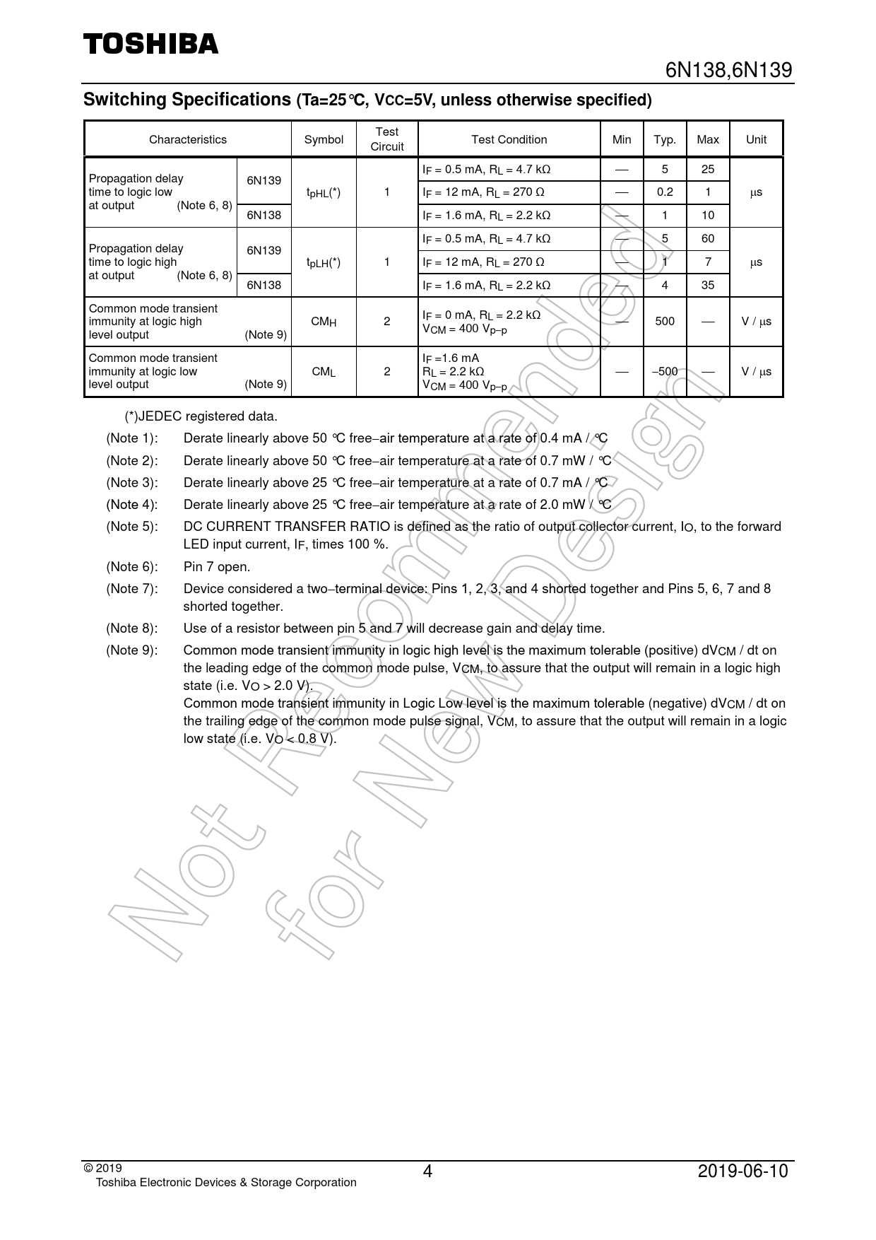
Test Characteristics Symbol Test Condition Min Typ. Max Unit Circuit IF = 0.5 mA, RL = 4.7 kΩ 5 25 Propagation delay 6N139 time to logic low tpHL(*) 1 IF = 12 mA, RL = 270 Ω 0.2 1 µs at output (Note 6, 8) 6N138 IF = 1.6 mA, RL = 2.2 kΩ 1 10 IF = 0.5 mA, RL = 4.7 kΩ 5 60 Propagation delay 6N139 time to logic high tpLH(*) 1 IF = 12 mA, RL = 270 Ω 1 7 µs at output (Note 6, 8) 6N138 IF = 1.6 mA, RL = 2.2 kΩ 4 35 Common mode transient I immunity at logic high CM F = 0 mA, RL = 2.2 kΩ H 2 500 V / µs V level output (Note 9) CM = 400 Vp−p Common mode transient IF =1.6 mA immunity at logic low CML 2 RL = 2.2 kΩ −500 V / µs level output (Note 9) VCM = 400 Vp−p (*)JEDEC registered data. (Note 1): Derate linearly above 50 °C free−air temperature at a rate of 0.4 mA / °C (Note 2): Derate linearly above 50 °C free−air temperature at a rate of 0.7 mW / °C (Note 3): Derate linearly above 25 °C free−air temperature at a rate of 0.7 mA / °C (Note 4): Derate linearly above 25 °C free−air temperature at a rate of 2.0 mW / °C (Note 5): DC CURRENT TRANSFER RATIO is defined as the ratio of output collector current, IO, to the forward LED input current, IF, times 100 %. (Note 6): Pin 7 open. (Note 7): Device considered a two−terminal device: Pins 1, 2, 3, and 4 shorted together and Pins 5, 6, 7 and 8 shorted together. (Note 8): Use of a resistor between pin 5 and 7 will decrease gain and delay time. (Note 9): Common mode transient immunity in logic high level is the maximum tolerable (positive) dVCM / dt on the leading edge of the common mode pulse, VCM, to assure that the output will remain in a logic high state (i.e. VO > 2.0 V). Common mode transient immunity in Logic Low level is the maximum tolerable (negative) dVCM / dt on the trailing edge of the common mode pulse signal, VCM, to assure that the output will remain in a logic low state (i.e. VO < 0.8 V). © 2019 4 2019-06-10 Toshiba Electronic Devices & Storage Corporation

 Купить 6N139 на РадиоЛоцман.Цены — от 11 до 1 808 ₽