Datasheet XDPL8210 (Infineon) - 7
| Производитель | Infineon |
| Описание | Digital Flyback Controller IC |
| Страниц / Страница | 50 / 7 — XDPL8210 Digital Flyback Controller IC. XDP™ Digital Power. Functional … |
| Версия | 01_00 |
| Формат / Размер файла | PDF / 699 Кб |
| Язык документа | английский |
XDPL8210 Digital Flyback Controller IC. XDP™ Digital Power. Functional block diagram. Figure 4

Модельный ряд для этого даташита
Текстовая версия документа
XDPL8210 Digital Flyback Controller IC XDP™ Digital Power Functional block diagram 2 Functional block diagram
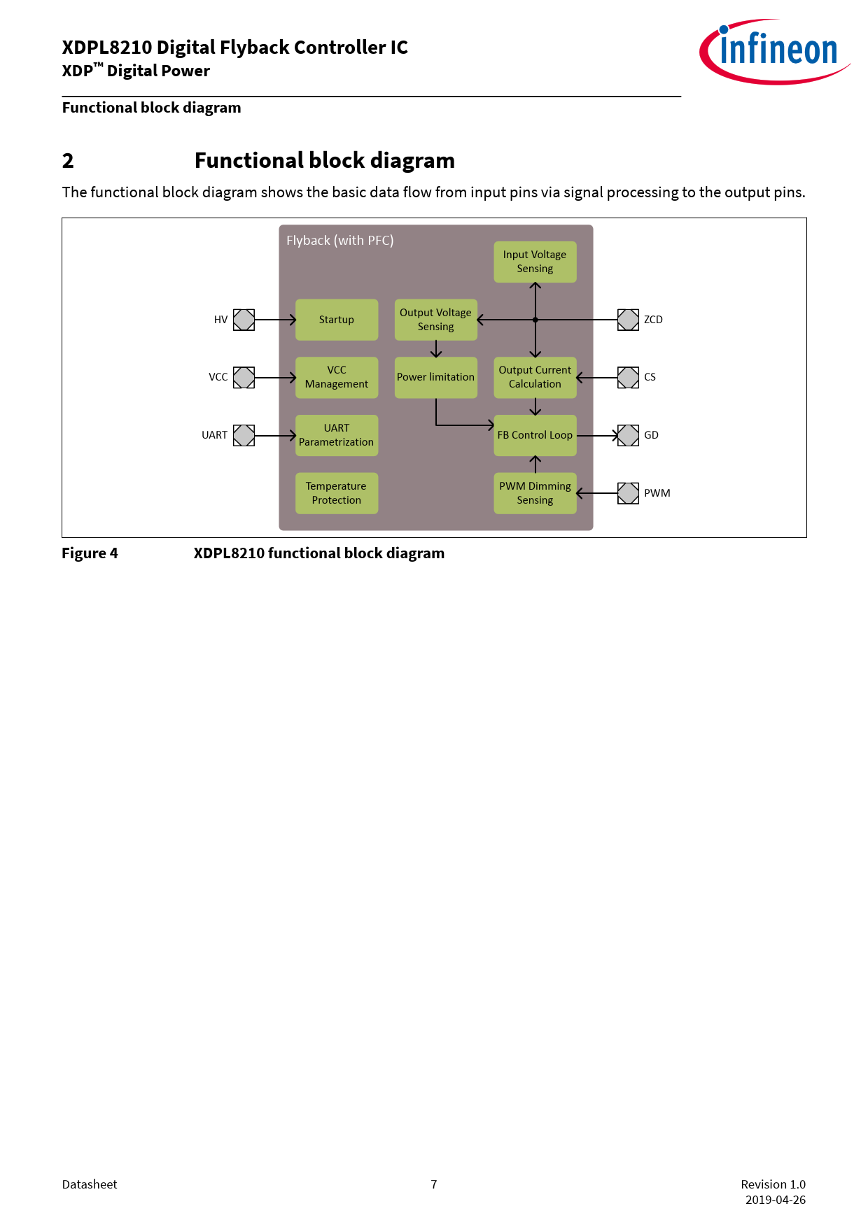
The functional block diagram shows the basic data flow from input pins via signal processing to the output pins. Flyback (with PFC) Input Voltage Sensing Output Voltage HV Startup ZCD Sensing VCC Output Current VCC Power limitation CS Management Calculation UART UART FB Control Loop GD Parametrization Temperature PWM Dimming PWM Protection Sensing
Figure 4 XDPL8210 functional block diagram
Datasheet 7 Revision 1.0 2019-04-26 Document Outline Features Product validation Potential applications Description Table of contents 1 Pin configuration 2 Functional block diagram 3 Functional description 3.1 Regulated mode 3.1.1 Constant current and limited power set-point 3.1.2 Multimode operation 3.1.3 Control loop initialization 3.2 Configurable gate voltage rising slope at GD pin 3.3 Startup 3.4 Line synchronization 3.5 Input voltage, output voltage and output current estimation 3.5.1 Input voltage estimation 3.5.2 Output voltage estimation 3.5.3 Output current estimation 3.6 Power factor correction 3.7 Dimming control 3.8 Protection features 3.8.1 Primary MOSFET overcurrent protection 3.8.2 Output undervoltage protection 3.8.3 Output overvoltage protection 3.8.4 Transformer demagnetization time shortage protection 3.8.5 Regulated mode peak output overcurrent protection 3.8.6 Minimum input voltage startup check and input undervoltage protection 3.8.7 Maximum input voltage startup check and input overvoltage protection 3.8.8 VCC undervoltage lockout 3.8.9 VCC overvoltage protection 3.8.10 IC overtemperature protection 3.8.11 Other protections 3.8.12 Protection reactions 4 Debug mode 5 List of Parameters 6 Electrical Characteristics and Parameters 6.1 Package Characteristics 6.2 Absolute Maximum Ratings 6.3 Operating conditions 6.4 DC Electrical characteristics 7 Package Dimensions 8 References Revision History Glossary ABM CC CRC DCM ECG EMI FB GUI IC LED LP MCU PC PF PFC PWM QRM1 THD UART USB UVLO Disclaimer
 Купить XDPL8210XUMA1 на РадиоЛоцман.Цены — от 51 до 4 571 ₽