Datasheet STSPIN32F0B (STMicroelectronics) - 10
| Производитель | STMicroelectronics |
| Описание | Advanced single shunt BLDC controller with embedded STM32 MCU |
| Страниц / Страница | 36 / 10 — STSPIN32F0B. Pin description. Figure 5. STSPIN32F0B SiP pin connection … |
| Формат / Размер файла | PDF / 6.5 Мб |
| Язык документа | английский |
STSPIN32F0B. Pin description. Figure 5. STSPIN32F0B SiP pin connection (top view). Table 6. STSPIN32F0B SiP pin description. No

29 предложений от 12 поставщиков Микросхема: ADVANCED SINGLE SHUNT BLDC CONTR |
| STSPIN32F0B
STMicroelectronics | 97 ₽ | |
| STSPIN32F0B
STMicroelectronics | 306 ₽ | |
| STSPIN32F0B
STMicroelectronics | 313 ₽ | |
| STSPIN32F0B
STMicroelectronics | по запросу | |
Модельный ряд для этого даташита
Текстовая версия документа
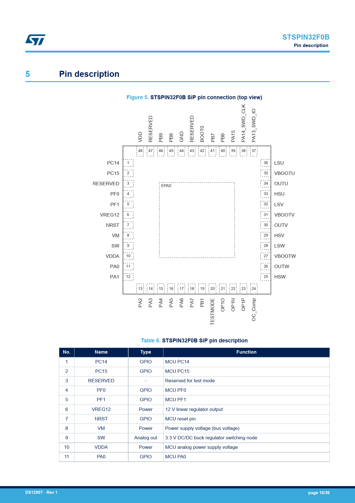
STSPIN32F0B Pin description 5 Pin description Figure 5. STSPIN32F0B SiP pin connection (top view)
D D D N V RESERVED PB9 PB8 G RESERVED BOOT0 PB7 PB6 PA15 PA14_SWD_CLK PA13_SWD_IO 48 47 46 45 44 43 42 41 40 39 38 37 PC14 1 36 LSU PC15 2 35 VBOOTU RESERVED 3 34 EPAD OUTU PF0 4 33 HSU PF1 5 32 LSV VREG12 6 31 VBOOTV NRST 7 30 OUTV VM 8 29 HSV SW 9 28 LSW VDDA 10 27 VBOOTW PA0 11 26 OUTW PA1 12 25 HSW 13 14 15 16 17 18 19 20 21 22 23 24 1 B PA2 PA3 PA4 PA5 PA6 PA7 P OP1O OP1N OP1P OC_Comp TESTMODE
Table 6. STSPIN32F0B SiP pin description No. Name Type Function
1 PC14 GPIO MCU PC14 2 PC15 GPIO MCU PC15 3 RESERVED - Reserved for test mode 4 PF0 GPIO MCU PF0 5 PF1 GPIO MCU PF1 6 VREG12 Power 12 V linear regulator output 7 NRST GPIO MCU reset pin 8 VM Power Power supply voltage (bus voltage) 9 SW Analog out 3.3 V DC/DC buck regulator switching node 10 VDDA Power MCU analog power supply voltage 11 PA0 GPIO MCU PA0
DS12907
-
Rev 1 page 10/36
Document Outline 1 Description 2 Block diagrams 3 Electrical data 3.1 Absolute maximum ratings 3.2 ESD protections 3.3 Recommended operating conditions 3.4 Thermal data 4 Electrical characteristics 5 Pin description 6 Device description 6.1 UVLO and thermal protections 6.1.1 UVLO on supply voltages 6.1.2 Thermal protection 6.2 DC/DC buck regulator 6.2.1 External optional 3.3 V supply voltage 6.3 Linear regulator 6.4 Standby mode 6.5 Gate drivers 6.6 Microcontroller unit 6.6.1 Memories and boot mode 6.6.2 Power management 6.6.3 High-speed external clock source 6.6.4 Advanced-control timer (TIM1) 6.7 Test mode 6.8 Operational amplifier 6.9 Comparator 6.10 ESD protection strategy 7 Application example 8 Package information 8.1 VFQFPN48 7 x 7 package information Revision history Contents List of tables List of figures
 Купить STSPIN32F0B на РадиоЛоцман.Цены — от 83 до 517 ₽