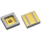
VLMU60CL..-280-125www.vishay.com Vishay Semiconductors
OPTICAL AND ELECTRICAL CHARACTERISTICS(Tamb = 25 °C, unless otherwise specified)
VLMU60CL00-280-125, ULTRAVIOLET PARAMETER TEST CONDITION SYMBOL MIN. TYP. MAX. UNITForward voltage IF = 20 mA VF 4.4 6.2 7.5 V Radiant power IF = 20 mA e 1.4 2.4 3.8 mW Peak wavelength IF = 20 mA p 270 280 290 nm Angle of half intensity IF = 20 mA - ± 62.5 - deg Thermal resistance junction to solder pin RthJS - 35 - K/W
Note• Tolerances: ± 11 % for e, ± 0.1 V for VF, ± 3 nm for p
TYPICAL CHARACTERISTICS(Tamb = 25 °C, unless otherwise specified) Axis Title Axis Title 60 10000 50 10000 50 ) 40 A A (m R in K/W: 125, 100, 75, 50 thJA (m 40 1000 1000 30 rrent rrent u ne ne ne ine u ne ine 30 rd C 1st li 2nd l 2nd li rd C 1st li a 2nd l a 20 2nd li 20 100 orw 100 orw F F - - I F 10 10 I F 0 10 0 10 0 20 40 60 80 100 0 1 2 3 4 5 6 7 8 T - Ambient Temperature (°C) V - Forward Voltage (V) amb F 2nd line 2nd line Fig. 1 - Maximum Forward Current vs. Ambient Temperature Fig. 3 - Forward Current vs. Forward Voltage Axis Title Axis Title 2.5 10000 1.0 10000 0.9 (mW) 2.0 0.8 ty 0.7 1000 Power 1000 1.5 tensi 0.6 n ne ne ne ne ine e I ine v 0.5 1st li ati 1st li 1.0 2nd li 2nd l 0.4 2nd li 2nd l el 100 R 100 - l 0.3 elative Radiant R I re - 0.5 0.2 l 0.1 Φ V re 0 10 0 10 0 10 20 30 40 50 250 270 290 310 330 350 I - Forward Current (mA) λ F - Wavelengths (nm) 2nd line 2nd line Fig. 2 - Relative Radiant Power vs. Forward Current Fig. 4 - Relative Spectral Power vs. Wavelength Rev. 1.1, 23-Jan-18
2Document Number: 84599 For technical questions, contact:
[email protected] THIS DOCUMENT IS SUBJECT TO CHANGE WITHOUT NOTICE. THE PRODUCTS DESCRIBED HEREIN AND THIS DOCUMENT ARE SUBJECT TO SPECIFIC DISCLAIMERS, SET FORTH AT www.vishay.com/doc?91000
 Купить VLMU60CL00-280 на РадиоЛоцман.Цены — от 1 541 до 1 767 ₽