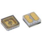
VLMU35CM..-280-120www.vishay.com Vishay Semiconductors
OPTICAL AND ELECTRICAL CHARACTERISTICS(Tamb = 25 °C, unless otherwise specified)
VLMU35CM..-280-120, ULTRAVIOLET PARAMETER TEST CONDITION SYMBOL MIN. TYP. MAX. UNITForward voltage IF = 100 mA VF 4 5 7 V Radiant power IF = 100 mA φe 8 12 - mW Ratio of radiant intensity/radiant power IF = 100 mA Ie/φe - 0.28 - sr-1 Peak wavelength IF = 100 mA λp 265 278 285 nm Angle of half intensity IF = 100 mA ϕ - ± 60 - ° Thermal resistance junction to solder pin RthJS - 15 - K/W Soldered on 20 x 20 x 1.7 (in mm) Thermal resistance junction to ambient R Al MCPCB thJA - 30 - K/W
Note• Tolerances: ± 11 % for φe, ± 0.1 V for VF, ± 3 nm for λp
RADIANT POWER CLASSIFICATION(IF = 100 mA)
GROUP MIN. MAX. UNITX3 8 10 X4 10 12 X5 12 14 mW X6 14 16 X7 16 18
PEAK WAVELENGTH CLASSIFICATION(IF = 100 mA)
GROUP MIN. MAX. UNITW1 265 285 nm
FORWARD VOLTAGE CLASSIFICATION(IF = 100 mA)
GROUP MIN. MAX. UNITVX 4 5 VY 5 6 V V0 6 7
Note• In order to ensure availability, single groups for radiant intensity, wavelength, and forward voltage will not be orderable. Only one group for radiant intensity, wavelength, and forward voltage will be shipped in any one reel Rev. 1.0, 29-Nov-2018
2Document Number: 84938 For technical questions, contact:
[email protected] THIS DOCUMENT IS SUBJECT TO CHANGE WITHOUT NOTICE. THE PRODUCTS DESCRIBED HEREIN AND THIS DOCUMENT ARE SUBJECT TO SPECIFIC DISCLAIMERS, SET FORTH AT www.vishay.com/doc?91000

 Купить VLMU35CM00-280-120 на РадиоЛоцман.Цены — от 258 до 426 022 ₽