Datasheet ADE7754 (Analog Devices)
| Производитель | Analog Devices |
| Описание | Polyphase Multifunction Energy Metering IC with Serial Port |
| Страниц / Страница | 44 / 1 — Polyphase Multifunction. Energy Metering IC with Serial Port. ADE7754. … |
| Формат / Размер файла | PDF / 538 Кб |
| Язык документа | английский |
Polyphase Multifunction. Energy Metering IC with Serial Port. ADE7754. FEATURES. High Accuracy, Supports IEC 687/61036

18 предложений от 15 поставщиков Многофазная многофункциональная измерительная ИС с последовательным портом |
| ADE7754ARZRL
Analog Devices | 181 ₽ | |
| ADE7754ARZRL
Analog Devices | 346 ₽ | |
| ADE7754ARZRL
Analog Devices | 364 ₽ | |
| ADE7754ARZRL
Analog Devices | 396 ₽ | |
Модельный ряд для этого даташита
Текстовая версия документа
Polyphase Multifunction Energy Metering IC with Serial Port ADE7754 FEATURES
the use of the ADE7754 in various power meter services such as
High Accuracy, Supports IEC 687/61036
3-phase/4-wire, 3-phase/3-wire, and 4-wire delta.
Compatible with 3-Phase/3-Wire, 3-Phase/4-Wire
In addition to rms calculation, active and apparent power infor-
and any Type of 3-Phase Services
mation, the ADE7754 provides system calibration features for
Less than 0.1% Error in Active Power Measurement over a
each phase (i.e., channel offset correction, phase calibration,
Dynamic Range of 1000 to 1
and gain calibration). The CF logic output provides instanta-
Supplies Active Energy, Apparent Energy, Voltage RMS,
neous active power information.
Current RMS, and Sampled Waveform Data Digital Power, Phase, and Input Offset Calibration
The ADE7754 has a waveform sample register that enables
On-Chip Temperature Sensor ( 4 C Typical after Calibration)
access to ADC outputs. The part also incorporates a detection
On-Chip User Programmable Thresholds for Line Voltage
circuit for short duration low or high voltage variations. The
SAG and Overdrive Detections
voltage threshold levels and the duration (number of half line
SPI Compatible Serial Interface with Interrupt
cycles) of the variation are user programmable.
Request Line (IRQ)
A zero-crossing detection is synchronized with the zero-crossing
Pulse Output with Programmable Frequency
point of the line voltage of each of the three phases. The infor-
Proprietary ADCs and DSP Provide High Accuracy over
mation collected is used to measure each line’s period. It is also
Large Variations in Environmental Conditions and Time
used internally to the chip in the line active energy and line
Single 5 V Supply
apparent energy accumulation modes. This permits faster and more accurate calibration of the power calculations. This signal
GENERAL DESCRIPTION
is also useful for synchronization of relay switching. The ADE7754 is a high accuracy polyphase electrical energy measurement IC with a serial interface and a pulse output. The Data is read from the ADE7754 via the SPI serial interface. The ADE7754 incorporates second order Σ-∆ ADCs, reference interrupt request output (IRQ) is an open-drain, active low circuitry, temperature sensor, and all the signal processing logic output. The IRQ output goes active low when one or more required to perform active, apparent energy measurements, and interrupt events have occurred in the ADE7754. A status regis- rms calculation. ter indicates the nature of the interrupt. The ADE7754 provides different solutions for measuring active The ADE7754 is available in a 24-lead SOIC package. and apparent energy from the six analog inputs, thus enabling
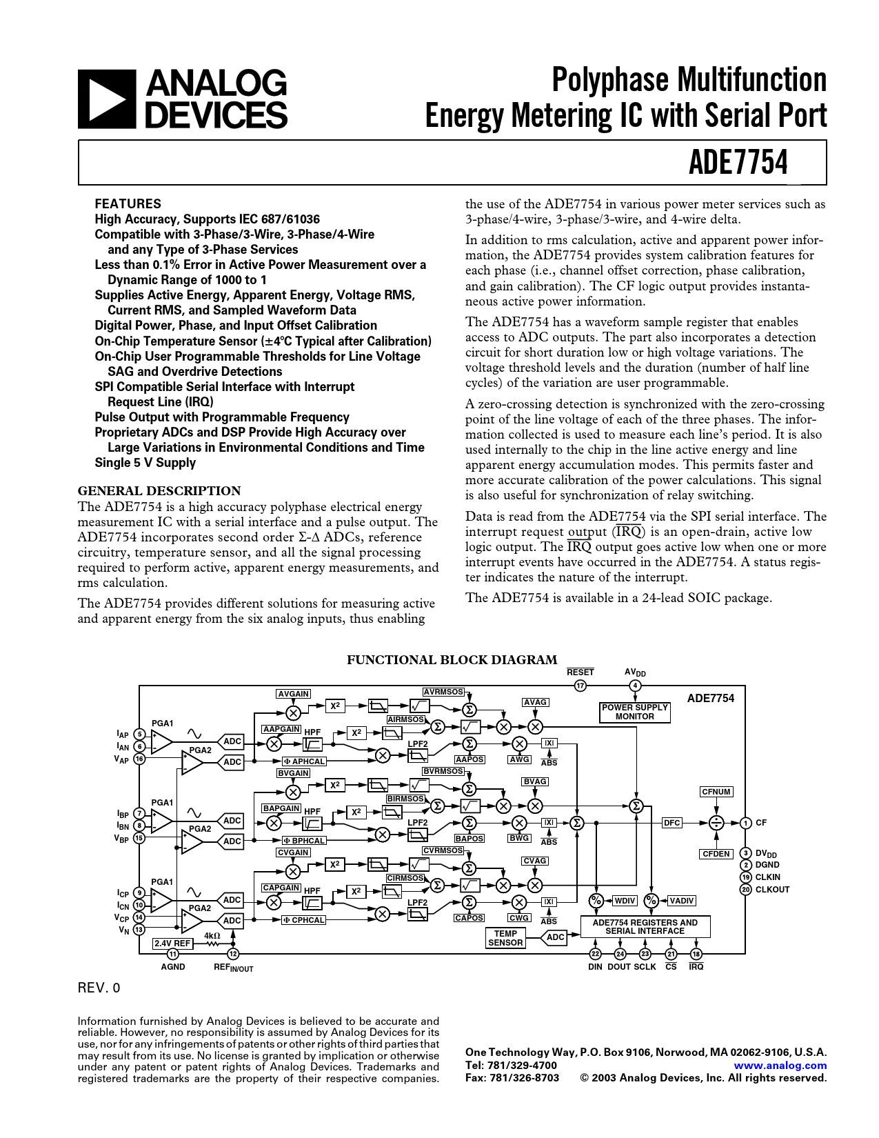
FUNCTIONAL BLOCK DIAGRAM RESET AVDD AVRMSOS AVGAIN ADE7754 X2 AVAG POWER SUPPLY AIRMSOS MONITOR PGA1 AAPGAIN I X2 HPF AP ADC LPF2 |X| IAN PGA2 VAP ADC APHCAL AAPOS AWG ABS BVRMSOS BVGAIN X2 BVAG CFNUM BIRMSOS PGA1 BAPGAIN I X2 HPF BP ADC LPF2 |X| DFC I CF BN PGA2 VBP ADC BPHCAL BAPOS BWG ABS CVRMSOS CVGAIN CFDEN DVDD X2 CVAG DGND CIRMSOS CLKIN PGA1 CAPGAIN I X2 HPF CLKOUT CP ADC LPF2 |X| % WDIV % VADIV ICN PGA2 VCP ADC CPHCAL CAPOS CWG ABS ADE7754 REGISTERS AND VN SERIAL INTERFACE 4k TEMP ADC 2.4V REF SENSOR AGND REFIN/OUT DIN DOUT SCLK CS IRQ
REV. 0 Information furnished by Analog Devices is believed to be accurate and reliable. However, no responsibility is assumed by Analog Devices for its use, nor for any infringements of patents or other rights of third parties that may result from its use. No license is granted by implication or otherwise
One Technology Way, P.O. Box 9106, Norwood, MA 02062-9106, U.S.A.
under any patent or patent rights of Analog Devices. Trademarks and
Tel: 781/329-4700 www.analog.com
registered trademarks are the property of their respective companies.
Fax: 781/326-8703 © 2003 Analog Devices, Inc. All rights reserved.
Document Outline FEATURES GENERAL DESCRIPTION FUNCTIONAL BLOCK DIAGRAM SPECIFICATIONS TIMING CHARACTERISTICS ABSOLUTE MAXIMUM RATINGS ORDERING GUIDE PIN CONFIGURATION PIN FUNCTION DESCRIPTIONS Typical Performance Characteristics TERMINOLOGY Measurement Error Phase Error Between Channels Power Supply Rejection ADC Offset Error Gain Error Gain Error Match POWER SUPPLY MONITOR ANALOG INPUTS ANALOG-TO-DIGITAL CONVERSION Antialias Filter CURRENT CHANNEL ADC Current Channel ADC Gain Adjust Current Channel Sampling VOLTAGE CHANNEL ADC ZERO-CROSSING DETECTION Zero-Crossing Timeout PERIOD MEASUREMENT LINE VOLTAGE SAG DETECTION SAG Level Set PEAK DETECTION Peak Level Set TEMPERATURE MEASUREMENT PHASE COMPENSATION ROOT MEAN SQUARE MEASUREMENT Current RMS Calculation Current RMS Gain Adjust Current RMS Offset Compensation Voltage RMS Calculation Voltage RMS Gain Adjust Voltage RMS Offset Compensation ACTIVE POWER CALCULATION Power Offset Calibration Reverse Power Information TOTAL ACTIVE POWER CALCULATION ENERGY CALCULATION Integration Times Under Steady Load Energy to Frequency Conversion No Load Threshold Mode Selection of the Sum of the Three Active Energies LINE ENERGY ACCUMULATION REACTIVE POWER CALCULATION TOTAL REACTIVE POWER CALCULATION Reactive Energy Accumulation Selection APPARENT POWER CALCULATION Apparent Power Offset Calibration TOTAL APPARENT POWER CALCULATION APPARENT ENERGY CALCULATION Integration Times under Steady Load LINE APPARENT ENERGY ACCUMULATION ENERGIES SCALING CHECK SUM REGISTER SERIAL INTERFACE Serial Write Operation Serial Read Operation INTERRUPTS Using Interrupts with an MCU Interrupt Timing ACCESSING THE ADE7754 ON-CHIP REGISTERS Communications Register Operational Mode Register (0Ah) Gain Register (18h) CFNUM Register (25h) Measurement Mode Register (0Bh) Waveform Mode Register (0Ch) Watt Mode Register (0Dh) VA Mode Register (0Eh) Interrupt Enable Register (0Fh) Interrupt Status Register (10h)/Reset Interrupt Status Register (11h) OUTLINE DIMENSIONS

 Купить ADE7754ARZRL на РадиоЛоцман.Цены — от 181 до 67 006 ₽