Datasheet LTC3119 (Analog Devices) - 7
| Производитель | Analog Devices |
| Описание | 18V, 5A Synchronous Buck-Boost DC/DC Converter |
| Страниц / Страница | 36 / 7 — Typical perForMance characTerisTics TA = 25°C, unless otherwise noted. … |
| Формат / Размер файла | PDF / 2.8 Мб |
| Язык документа | английский |
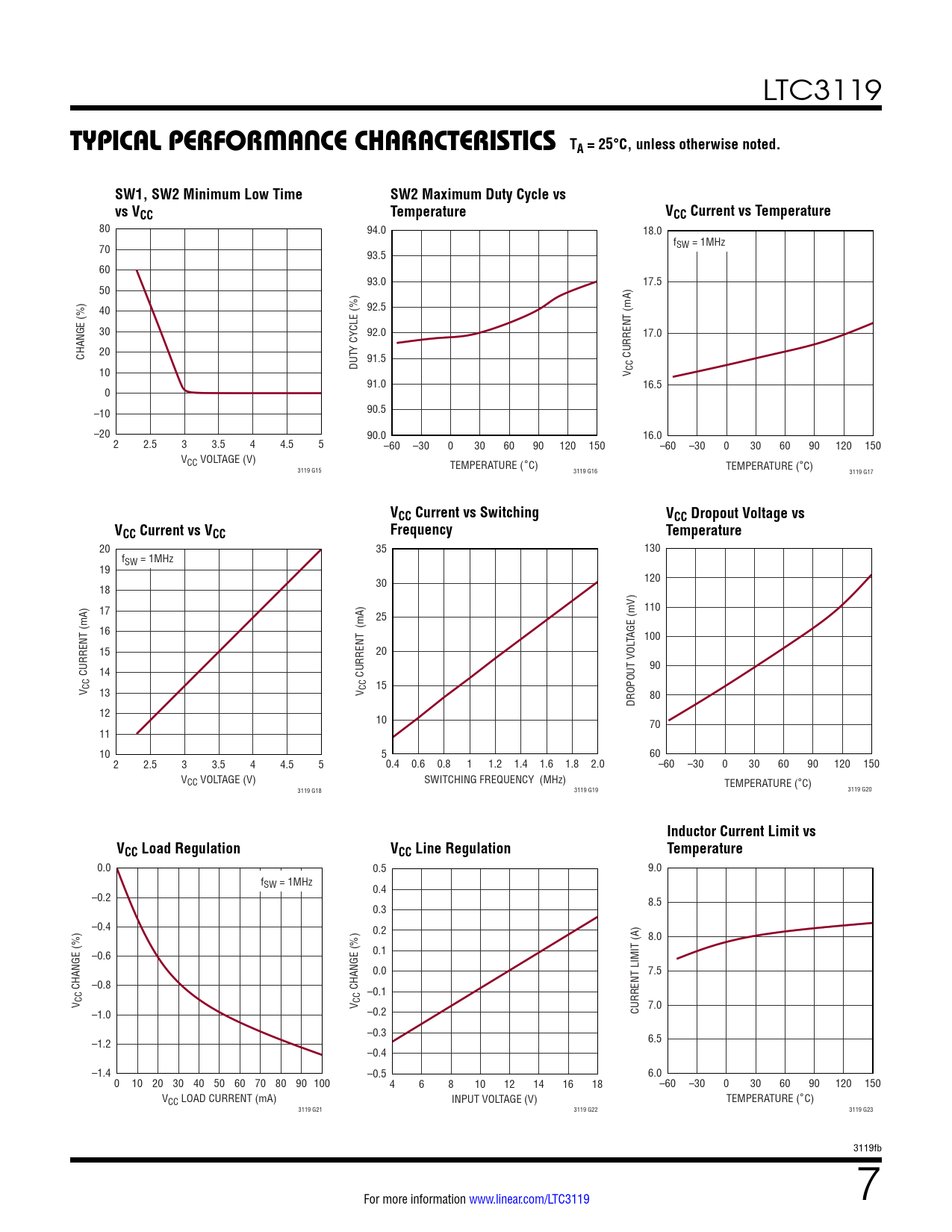
Typical perForMance characTerisTics TA = 25°C, unless otherwise noted. SW1, SW2 Minimum Low Time. SW2 Maximum Duty Cycle vs

Модельный ряд для этого даташита
Текстовая версия документа
LTC3119
Typical perForMance characTerisTics TA = 25°C, unless otherwise noted. SW1, SW2 Minimum Low Time SW2 Maximum Duty Cycle vs vs VCC vs V Temperature VCC V Current vs Temperature CC Current vs T
80 94.0 18.0 f 70 SW = 1MHz 93.5 60 93.0 17.5 50 92.5 40 30 92.0 17.0 Y CYCLE (%) 20 CHANGE (%) 91.5 CURRENT (mA) DUT 10 V CC 91.0 16.5 0 90.5 –10 –20 90.0 16.0 2 2.5 3 3.5 4 4.5 5 –60 –30 0 30 60 90 120 150 –60 –30 0 30 60 90 120 150 VCC VOLTAGE (V) TEMPERATURE (°C) TEMPERATURE (°C) 3119 G15 3119 G16 3119 G17
VCC Current vs Switching VCC Dropout Voltage vs V Current vs V Frequency CC Current vs V CC CC V Temperature CC CC Current vs Switching Frequency
20 35 130 fSW = 1MHz 19 30 120 18 17 110 25 16 TAGE (mV) 100 15 20 14 90 CURRENT (mA) CURRENT (mA) V CC 15 13 V CC 80 DROPOUT VOL 12 10 70 11 10 5 60 2 2.5 3 3.5 4 4.5 5 0.4 0.6 0.8 1 1.2 1.4 1.6 1.8 2.0 –60 –30 0 30 60 90 120 150 VCC VOLTAGE (V) SWITCHING FREQUENCY (MHz) TEMPERATURE (°C) 3119 G18 3119 G19 3119 G20
Inductor Current Limit vs VCC Load Regulation V CC CC Line Regulation Temperature
0.0 0.5 9.0 fSW = 1MHz 0.4 –0.2 8.5 0.3 –0.4 0.2 8.0 0.1 –0.6 0.0 7.5 –0.8 CHANGE (%) CHANGE (%) –0.1 V CC V CC 7.0 –1.0 –0.2 CURRENT LIMIT (A) –0.3 –1.2 6.5 –0.4 –1.4 –0.5 6.0 0 10 20 30 40 50 60 70 80 90 100 4 6 8 10 12 14 16 18 –60 –30 0 30 60 90 120 150 VCC LOAD CURRENT (mA) INPUT VOLTAGE (V) TEMPERATURE (°C) 3119 G21 3119 G22 3119 G23 3119fb For more information www.linear.com/LTC3119 7 Document Outline Features Applications Typical Application Description Absolute Maximum Ratings Pin Configuration Order Information Electrical Characteristics Typical Performance Characteristics Pin Functions Block Diagram Operation Introduction PWM Mode Operation VCC Regulator Current Mode Control Error Amplifiers Current Limit and Zero Current Detection Soft-Start Maximum Power Point Control (MPPC) Burst Mode Operation Power Good Indicator Thermal Considerations Applications Information Typical Applications Package Description Revision History Typical Application Related Parts

 Купить LTC3119EFE#TRPBF на РадиоЛоцман.Цены — от 318 до 942 ₽