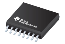
Datasheet Texas Instruments UC2525BDWTRG4 — Даташит
| Производитель | Texas Instruments |
| Серия | UC2525B |
| Модель | UC2525BDWTRG4 |

Регулирующие широтно-импульсные модуляторы 16-SOIC от -40 до 85
Datasheets
Regulating Pulse Width Modulators datasheet
PDF, 1.6 Мб, Файл опубликован: 5 сен 1999
Выписка из документа
Цены
 Купить UC2525BDWTRG4 на РадиоЛоцман.Цены — от 240 до 685 ₽ Купить UC2525BDWTRG4 на РадиоЛоцман.Цены — от 240 до 685 ₽12 предложений от 11 поставщиков Voltage Mode PWM Controller 400mA 400kHz 16Pin SOIC T/R | |||
| UC2525BDWTRG4 Texas Instruments | 240 ₽ | ||
| UC2525BDWTRG4 Texas Instruments | 313 ₽ | ||
| UC2525BDWTRG4 Texas Instruments | 315 ₽ | ||
| UC2525BDWTRG4 Texas Instruments | по запросу | ||
Статус
| Статус продукта | В производстве (Рекомендуется для новых разработок) |
| Доступность образцов у производителя | Нет |
Корпус / Упаковка / Маркировка
| Pin | 16 |
| Package Type | DW |
| Industry STD Term | SOIC |
| JEDEC Code | R-PDSO-G |
| Package QTY | 2000 |
| Carrier | LARGE T&R |
| Маркировка | UC2525BDW |
| Width (мм) | 7.5 |
| Length (мм) | 10.3 |
| Thickness (мм) | 2.35 |
| Pitch (мм) | 1.27 |
| Max Height (мм) | 2.65 |
| Mechanical Data | Скачать |
Параметры
| Control Method | Voltage |
| Duty Cycle(Max) | 49 % |
| Frequency(Max) | 500 kHz |
| Frequency(Min) | 0.1 kHz |
| Gate Drive(Typ) | 0.5 A |
| Рабочий диапазон температур | от -40 до 85 C |
| Package Group | SOIC |
| Rating | Catalog |
| Special Features | Error Amplifier,Multi-topology,Soft Start,Synchronization Pin |
| Topology | Boost,Buck,Flyback,Forward,Half-Bridge,Push-Pull |
| UVLO Thresholds On/Off | 7.0/6.5 В |
| Vin(Max) | 35 В |
| Vin(Min) | 8 В |
Экологический статус
| RoHS | Совместим |
Application Notes
- DN-36 UC1525B/UC1527B Devices - Comparison Summary to UC1525A/27A DevicesPDF, 19 Кб, Файл опубликован: 5 сен 1999
The UC1525B and UC1527B are enhanced versions of the previous generation of UC1525A and UC1527A devices. They are pin-for-pin compatible and direct replacements for the A versions in almost all applications. The table in this design note compares the two sets of devices. Significant improvements have been made in the 5.1 V reference voltage and the output drivers as itemized in the table. - DN-62 Switching Power Supply Topology Voltage Mode vs. Current ModePDF, 66 Кб, Файл опубликован: 5 сен 1999
This design note explains the differences between voltage-mode and current-mode switching power supply topologies. It includes a circuit diagram for each mode and suggests criteria for choosing which mode to use.
Модельный ряд
Серия: UC2525B (2)
- UC2525BDWTR UC2525BDWTRG4
Классификация производителя
- Semiconductors > Power Management > Offline and Isolated DC/DC Controllers and Converters > PWM and Resonant Controller


